
A Hydraulic Press Machine Drawing is more than a simple sketch of steel plates, cylinders, and hydraulic lines. It is a technical representation that explains how the machine is built, connected, and expected to operate. Engineers use it to study dimensions, material choices, load paths, tolerances, and safety features before fabrication begins. A clear drawing may show the press frame, moving ram, worktable, hydraulic cylinder, pump, reservoir, pressure gauge, and control valves.
Details matter here.
For example, a drawing can reveal whether the ram is properly aligned with the worktable. It may also identify weak joints, limited access for maintenance, or insufficient space around hydraulic fittings. Experienced designers usually compare calculated pressing forces with the frame’s rated capacity and operating conditions. They also check whether seals, hoses, guards, and emergency controls are represented accurately. A missing symbol can create confusion during assembly or inspection.
However, no drawing is perfect.
Real machines often expose issues that remain invisible on paper. Vibration, fluid temperature, production tolerances, and operator access can challenge an otherwise careful design. For this reason, a professional Hydraulic Press Machine Drawing should be reviewed by qualified engineers and updated after testing. Revision notes, scale information, section views, and recognized engineering symbols improve reliability. The best drawing supports communication between designers, fabricators, technicians, and inspectors. It should be precise, readable, and honest about its limitations. That honesty helps prevent costly mistakes and encourages safer machine development.
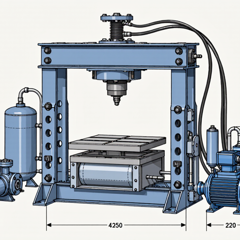
A hydraulic press machine drawing is a technical plan that shows how a press is arranged, built, or installed. It may include front, side, and top views, along with dimensions, material notes, and component labels. The drawing helps engineers, fabricators, and maintenance staff work from the same reference. In practice, it can reduce guesswork when checking whether a cylinder, frame, and worktable fit together. Small details matter.
The purpose depends on the drawing’s scope. A general arrangement drawing explains the machine’s overall footprint and major parts. A detailed fabrication drawing may specify plate thickness, weld locations, and hole sizes. Hydraulic diagrams can show how pumps, valves, hoses, and cylinders connect, but they do not replace mechanical drawings. A useful drawing also identifies units, tolerances, and revision status. If these are missing, a dimension can be misread, even by an experienced technician. Drawings are not perfect; they can lag behind changes made on the shop floor.
A hydraulic press machine drawing is more than a construction sketch. It explains how force moves through the system. Key symbols identify the pump, reservoir, relief valve, directional valve, cylinder, and pressure gauge. ISO 1219-1 defines graphical symbols for fluid-power systems, helping technicians read the same circuit across different workplaces. A solid line usually represents a working hydraulic path. A dashed line often shows a pilot or control connection. Flow arrows matter. One reversed arrow can change cylinder movement.
The main components should appear in a logical sequence. The reservoir stores oil, while the pump sends pressurized fluid toward the control valve. The relief valve protects the circuit from excessive pressure. The cylinder converts fluid pressure into ram force. A pressure gauge gives operators a visible reference during testing. A 2023 labor report recorded 5,283 fatal workplace injuries in the United States, reminding designers that clear safety details cannot be decorative. Guards, emergency stops, pressure limits, and locked maintenance points deserve clear symbols. Small details matter. I have seen drawings that looked technically correct but lacked hose identification. That weakness can delay troubleshooting and invite mistakes. A useful drawing also includes port labels, flow direction, working pressure, cylinder stroke, and component references. Some diagrams still omit return-line filters. That omission deserves review.
A hydraulic press machine drawing turns force and motion into details that engineers can inspect. It typically shows the cylinder, pump, reservoir, valves, frame, and moving platen. Hydraulic lines connect these parts, while arrows indicate fluid direction and actuator movement. ISO 1219-1 provides standardized symbols for fluid-power diagrams, helping readers distinguish a directional valve from a pressure-control valve. The drawing should also state working pressure, cylinder bore, rod diameter, and stroke. Without those values, the picture may look complete but remain difficult to verify.
Force begins with pressure acting on piston area: F = P × A. For example, a 100 mm bore cylinder at 20 MPa produces about 157 kN on its full-bore side, before losses. The return stroke differs because the rod reduces the effective area. A useful drawing marks both directions, pressure limits, and the points where pressure is measured. The U.S. Department of Energy’s Improving Pumping System Performance sourcebook estimates that pumping systems consume about 16% of U.S. industrial electricity; this is not a press-specific figure, but it makes pump load and operating conditions worth documenting. Small errors matter. A line arrow alone cannot show whether a press holds position under load. Add valve states and motion limits where needed, then check whether the diagram matches the actual machine. Real systems can be messier than the drawing. That deserves a second look.
A hydraulic press machine drawing uses mechanical views and hydraulic symbols to show the press structure, fluid-power circuit, component connections, and operating motion.
| Drawing element | How it is represented | What it communicates | Typical drawing details |
|---|---|---|---|
| Press frame and bed | Front, side, and plan views; outlines and dimension lines | The machine’s overall structure and work area | Frame opening, bed size, overall height, and mounting points |
| Hydraulic cylinder | A cylinder-and-piston symbol in the circuit; a physical outline in the assembly view | Where hydraulic pressure produces linear ram motion | Bore, rod diameter, stroke, mounting style, and port locations |
| Hydraulic pump | A pump symbol, commonly shown as a circle with a filled triangle indicating flow direction | The source of fluid flow in the power circuit | Flow rate, drive connection, rotation direction, and inlet/outlet ports |
| Reservoir and return line | A tank symbol connected to the circuit by solid hydraulic lines | Fluid storage and the path back to the tank | Tank capacity, return connections, and any filter or cooler locations |
| Directional control valve | Adjacent boxes with arrows and blocked-port marks; ports are commonly labeled P, T, A, and B | How flow is routed to extend, retract, or hold the cylinder | Valve positions, actuation method, spring return, and port connections |
| Pressure-relief valve | A pressure-control valve symbol connected between the pressure line and tank | Pressure limitation that helps protect the circuit from excessive pressure | Set pressure, adjustment method, and relief-flow path |
| Pressure gauge and sensor | A gauge symbol or instrument tag connected to a pressure line | Where circuit pressure is measured or monitored | Measurement location, range, and instrument identification |
| Hydraulic lines and connections | Solid lines for working lines; line crossings and junctions are distinguished by drafting convention | Fluid routes and component interconnections | Line identification, connection points, hose or tube routing, and fittings |
| Force and motion annotations | Arrows, stroke limits, and notes adjacent to the ram or cylinder | The direction and extent of press movement | Advance, return, working stroke, and specified force or pressure values |
Hydraulic symbols and line conventions are commonly based on ISO 1219. Actual symbols, dimensions, pressure settings, and ratings depend on the specific press design and its engineering documentation.
A hydraulic press machine drawing is more than a picture of a frame and cylinder. It combines dimensions, assembly details, and often a hydraulic schematic. Read it as a set of connected clues. Keep the drawing number and revision visible; an outdated sheet can show parts that no longer match the machine.
Start with the title block. Check units, scale, projection method, and revision date before measuring anything. Then compare the front, side, and plan views. A cylinder shown above the bed in one view should align with its mounting points in another. Look for section marks and detail bubbles, which reveal hidden features such as guideways or bolted joints. Never rely on scale alone. Written dimensions take priority.
Next, trace the hydraulic lines from the pump through valves to the cylinder, following symbols and line labels rather than guessing from their appearance. Note pressure ratings, hose sizes, and any stated test conditions. A relief valve, for example, affects how the circuit controls pressure; its symbol is not merely decoration. Check the bill of materials against the assembly view, and read tolerances carefully around moving or fitted parts. If a dimension, symbol, or revision is unclear, pause and ask a qualified designer to verify it. Even experienced readers miss things. I sometimes need to revisit a drawing after spotting a mismatch between its views.
What Is a Hydraulic Press Machine Drawing?
Common Types and Applications of Hydraulic Press Drawings
Hydraulic press drawings turn a machine concept into dimensions, components, and assembly instructions. They may show the full press, a hydraulic circuit, or a detailed part such as a cylinder mount. Each view serves a different purpose. A section drawing, for example, can reveal how a ram, seals, and guide rails fit together.
Common types include general arrangement drawings, fabrication drawings, hydraulic schematics, and installation layouts. A fabrication drawing may specify plate thickness, hole positions, and weld details. A hydraulic schematic maps pumps, valves, and lines, helping technicians trace how pressure reaches the cylinder. Small omissions matter. A missing port label can slow assembly or maintenance.
These drawings support applications such as metal forming, powder compaction, and plastic molding. They also help connect presses with automated production cells. The International Federation of Robotics reported 541,302 industrial robot installations worldwide in 2023 in its World Robotics 2024 report. That figure reflects the wider shift toward automation, where clear press layouts and interface details help teams plan robot access, guarding, and material flow. Still, a drawing is only as useful as its assumptions; real floor space and operator reach deserve careful checking.
Example design points only—not standard or recommended capacities. Actual press force varies by machine design and application. Hydraulic press drawings typically specify the frame, cylinder, platen, dimensions, and rated force; these details support tasks such as assembly, forming, molding, and deep drawing.
It shows how oil, pressure, and motion travel through the machine. The drawing usually includes the reservoir, pump, valves, cylinder, frame, and moving platen. Details matter.
A solid line usually represents the main hydraulic path. A dashed line often indicates a pilot or control connection. Always check the drawing legend.
Arrows show the direction of fluid movement and cylinder travel. One reversed arrow can change the ram’s movement. That small mistake matters.
The pump sends pressurized oil toward the control valve. The relief valve limits excessive pressure and protects the circuit. A gauge provides a visible pressure reference during testing.
Hydraulic force follows the formula F = P × A. A 100-millimeter bore at 20 MPa produces about 157 kN before losses. Real output may be lower.
The rod reduces the effective piston area during retraction. Therefore, return force differs from full-bore pressing force. Mark both directions clearly.
Include the bore, rod diameter, stroke, working pressure, and motion limits. These values help technicians verify the design. Without them, the drawing can look complete but remain uncertain.
Show guards, emergency stops, pressure limits, and locked maintenance points. Identify hoses, ports, and pressure-measurement locations. A technically correct drawing can still be unsafe.
A return-line filter helps control contamination before oil returns to the reservoir. Some diagrams omit it. That omission deserves review.
Yes, but real systems can be messier than the drawing. Check valve states, hose routing, flow direction, and pressure readings. A second look is worthwhile.
A Hydraulic Press Machine Drawing is a technical guide that explains the structure, operation, and relationships between the main parts of a hydraulic press system. It is used to support design, manufacturing, installation, maintenance, and troubleshooting. The drawing may show the frame, cylinder, piston, hydraulic pump, reservoir, valves, hoses, pressure gauges, and electrical or control connections. Standard symbols and labeled lines help readers identify each component and understand how hydraulic fluid moves through the system.
To interpret a Hydraulic Press Machine Drawing, begin by reviewing the title, scale, legend, and component labels. Then follow the fluid path from the reservoir to the pump, control valves, cylinder, and return line. Arrows and pressure indicators explain the direction of flow, while the cylinder and piston illustrate how hydraulic pressure becomes linear force and motion. Drawings may represent different press designs, including single-acting or double-acting systems, and can be applied to forming, bending, pressing, assembly, and testing operations.
